Great Tips About How To Draw Involute Gears

Tutorial: How To Model Involute Gears In Solidworks And Show Design Intent. | Grabcad Tutorials
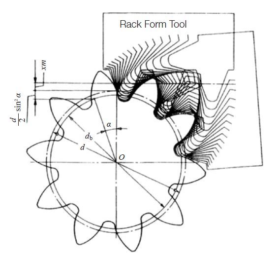
Involute Tooth Profile | Khk Gears

Tutorial: How To Model Involute Gears In Solidworks And Show Design Intent. | Grabcad Tutorials
The Involute Curve, Drafting A Gear In Cad And Applications

Creating Involute Gears In Cad | Fictiv

Involute Curve - Youtube
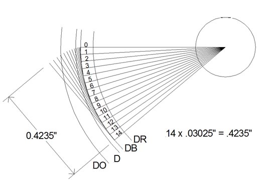
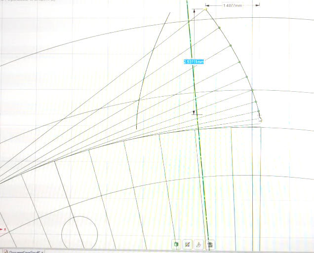
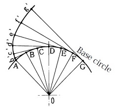
19) you can now draw the involute in a new skatch using the constructed points.
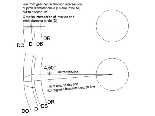
How to draw involute gears. The units for inv α is radians. We draw a circle from the center to that point. Check the rationale here or here.
In this example we will draw the 36 tooth, 24 pitch spur gear. A new involute has to be drawn for. (see figure 12) parallel the vertical line to the right using the distance from centers formula for each gear.
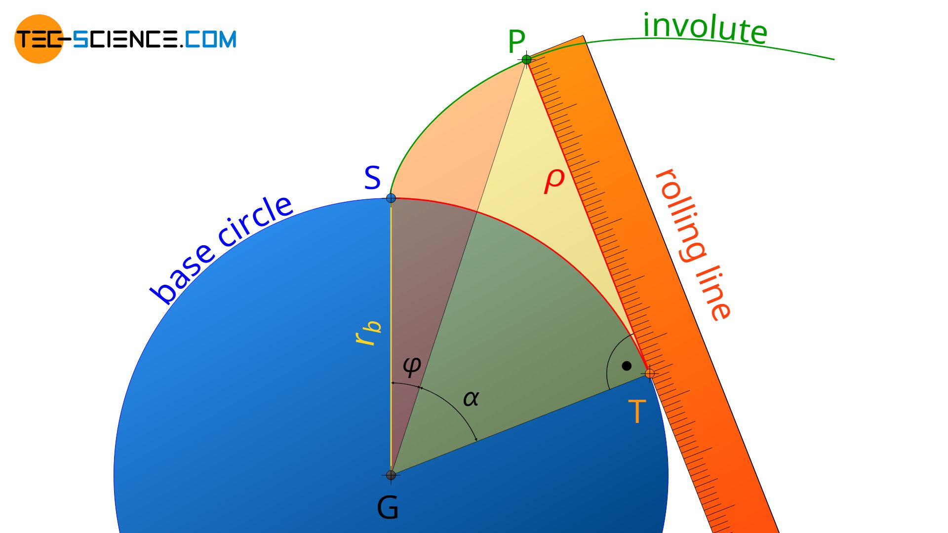
Begin by laying out the pitch, root. Θ is called involute rolling angle. Draw a horizontal line 10 long, then draw a vertical line from the left end 2 down.
This video details the process of drawing an involute spur gear by hand in solidworks. How to calculate the involute of the circle for gear tooth design.this video follows on from part 1 which details how gears of different diameters interact o. The formulas and sketch descriptions are used in the autocad gear procedure for internal and external.
After, we divide the line. In fig.3.3, invα stands for involute angle (involute α). When drawing an involute, you draw one side of one tooth, mirror that to make a whole tooth, and that copy that around your gear the right number of times.
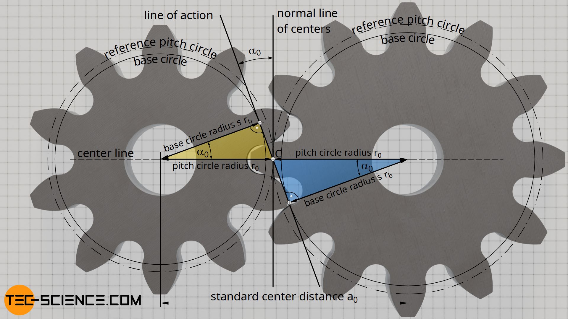
The circle is called the base circle of the involute. Using this example you will be able to draw a spur gear having any number of teeth and pitch. With the center of the base circle at the origin of a coordinate system, the involute curve can be.
I design my true involute internal gears with autocad.
Involute Gear Profile | Khk Manufacturer

Creating Involute Gears In Cad | Fictiv
Construction And Design Of Involute Gears - Tec-science
The Involute Curve, Drafting A Gear In Cad And Applications
Involute Gears, And How Not To Get Frustrated When Designing Them

Engineer-mechanical:inventor-gears - Jeffery J Jensen Wiki

Involute Gears
Involute Gear - Wikipedia
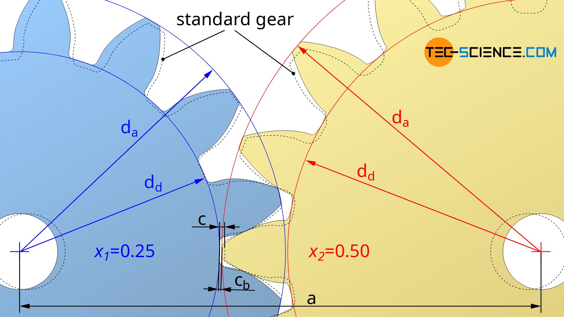
Calculation Of Involute Gears - Tec-science
Involute Tooth Profile | Khk Gears

Involute Gear - Youtube
Calculation Of Involute Gears - Tec-science

Involute Gear Profile | Khk Gears Profile, Reference,
